Guidelines for Choosing Valve Electric Actuators
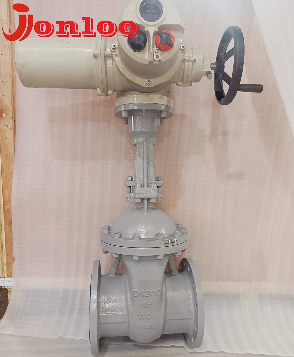
The opening and closing of valves are managed by electric valve actuators. They function with many valve types, including as ball and butterfly valves, and can produce either linear or rotary motion. Electric valve actuators are extremely useful for controlling systems that are difficult to access or dispersed over a wide region because they react to commands via remote control or centralized process control systems. Process control systems enable enterprises to automate processes and boost system dependability by controlling electric actuators with scheduled and programmed commands from a centralized system.
In general, electric valve actuators are become more responsive, sophisticated, and user-friendly. What you need to know about these parts' operation and what's required to install and operate them is covered in the tutorial that follows.
Generally speaking, the following criteria should be used while choosing valve electric actuators:
1. Operational torque
The output torque of the electric actuator should be 1.2 to 1.5 times the maximum working torque of the valve. This is the most crucial factor to consider when choosing electric valve devices.
2. Systems for controlling the thrust valve's electric device
There are two primary methods for controlling the thrust valve's electric device: either configure a thrust disc and convert the output torque into output thrust via the thrust disc's valve stem nut, or output torque can be output directly without the need for a thrust disc.
3. Number of output shaft rotation circle
The number of output shaft rotations of the valve electric device is determined by the valve's nominal diameter, valve stem pitch, and number of thread heads. This number is determined using the formula M=H/ZS, where M is the total number of rotations the device must meet, H is the valve's opening height, S is the valve stem's transmission thread pitch, and Z is the head count of the valve.
4. Diameter of the stem
When it comes to the multi-rotary class of open-stem valves with stem diameter, a valve cannot be constructed into an electric valve if the maximum stem diameter permitted by the electric device is not able to pass through the valve stem. As a result, the rising stem valve's outer diameter must be less than the inner diameter of the electric device's hollow output shaft. Although the valve stem diameter for non-rising stem valves in partial rotation valves and multi-rotary valves does not need to be taken into account, the valve stem diameter and keyway size should be carefully taken into account throughout the selection process to guarantee proper functioning following assembly.
5. Output speed
The water hammer phenomena can easily be caused if the valve opens and closes too quickly. Therefore, depending on various usage scenarios, the proper opening and shutting speed should be chosen.
6. Particular requirements
One particular necessity for valve electric actuators is that they have to be able to limit axial force or torque. Torque-limiting couplings are typically used in valve electric devices. The control torque of the electric device is also determined after its specification has been established. In most cases, it operates within a set duration and the motor won't overload.
However, the following circumstances could lead to overloading:
One is that the motor stops spinning because the power supply voltage is low and the necessary torque cannot be produced;
The second is to inadvertently put the torque limiting mechanism above the stopping torque, which results in persistently high torque generation and the motor ceasing to rotate;
The third is sporadic use, which causes heat buildup that is higher than the motor's permitted temperature rise;
Fourth, the torque limiting mechanism's circuit faults for an unknown reason, producing excessive torque;
The motor's thermal capacity is comparatively reduced due to an excessively high operating ambient temperature, which is the fifth reason.
Fuse, over current relays, thermal relays, thermostats, and other devices were once used to protect motors; however, each of these devices had pros and cons of its own. For equipment subject to changeable load, like electric gadgets, there is no completely dependable protection technique.
As a result, a variety of combination techniques must be used, which may be broadly divided into two categories: determining the degree to which the motor's input current is increasing or decreasing and determining the motor's internal heating condition. The time buffer provided by the motor's thermal capacity must be taken into account in each of these approaches.
Typically, the following is the fundamental overload protection technique:
(1) Employ a thermostat to prevent overloading the motor when it is running continuously or jogging;
(2) To prevent the motor from stalling, thermal relays are employed;
(3) Use fuses or over current relays to prevent short circuit accidents.
Electric valve actuators can be operated by varying the torque, axial thrust, or stroke magnitude. They are an essential tool for remote control, automatic control, and valve programming.
To avoid overloading, the right choice of valve electric devices is essential (working torque higher than control torque).
