Bolted Bonnets vs. Pressure Seals for Valves
On this page
Valves intended for high pressure service—typically above 170 bar—use pressure seal construction. Unlike other constructions where an increase in internal pressure tends to cause leaks in the body-Bonnet joint, the unique feature of the prThe sealing force increases with increasing internal pressure. The Bonnet assembly can be easily disassembled by dropping it into the body cavity and using a push pin to drive out the four-segmental thrust rings.
The sealing force increases with increasing internal pressure. The Bonnet assembly can be easily disassembled by dropping it into the body cavity and using a push pin to drive out the four-segmental thrust rings.
As boiler, HRSG, and pipe system pressure/temperature envelopes are pushed further by designers, pressure seal valves—which rely on comparatively straightforward design principles—have demonstrated their capacity to manage progressively more demanding fossil and combined-cycle steam isolation applications. Pressure seal valves are generally offered in size ranges of 2 to 24 inches and ASME B16.34 pressure classes of 600 to 2500; however, certain manufacturers can fulfill special application requirements that require larger diameters and higher ratings.
Pressure seal valves come in a variety of material qualities, including F316H forged and appropriate austenitic cast grades for temperatures above 500°C; A105 forged and Gr. WCB cast; alloy F22 forged and Gr. WC9 cast; F11 forged and Gr. WC6 cast; and austenitic stainless F316 forged and Gr. CF8M cast.
The origins of the pressure seal design concept date back to the mid-1900s, when valve manufacturers started developing alternatives to the conventional bolted-Bonnet method of sealing the body/Bonnet joint due to constantly rising pressures and temperatures (mainly in power applications). In addition to offering superior pressure boundary sealing integrity, numerous pressure seal valve designs were substantially lighter than their bolted Bonnet Valve equivalents. Let's compare the body-to-Bonnet sealing mechanism of pressure seals and bolted Bonnets in order to better understand the pressure seal design concept. The typical Bolted Bonnet valve is shown in Fig. 1. A gasket of the appropriate design or material is inserted between the flange faces to aid in sealing, and the body and bonnet flanges are fastened together with studs and nuts. To achieve the best sealing, studs, nuts, and bolts are tightened to specified torques according to a pattern specified by the manufacturer. On the other hand, the possibility of leakage through the body/Bonnet joint also rises with system pressure.
Let's now examine the pressure seal joint that is shown in Fig. 2. Take note of how the various body/Bonnet joint configurations differ. "Bonnet take-up bolts" are a common feature of pressure seal designs, which enable the bonnet to be pulled up and sealed against the pressure seal gasket. Consequently, a seal is formed between the gasket and the valve body's inner diameter (I.D.).
The thrust ring is segmented to maintain the load. The pressure seal design is so beautiful because it increases the load on the Bonnet and, by extension, the pressure seal gasket, as system pressure rises. As a result, in pressure seal valves, the possibility of leakage through the body/bonnet joint diminishes with increasing system pressure.
When it comes to main steam, feedwater, turbine bypass, and other power plant systems that need valves that can withstand the difficulties of high pressure and temperature applications, this design approach has clear advantages over bolted Bonnet Valves.
However, the same transient system pressure that helped in sealing also severely harmed the integrity of the pressure seal joint as operating pressures and temperatures rose over time and peaking plants were introduced. The gasket itself is one of the main parts that seals the pressure seal valve. Iron or soft steel were used to make pressure seal gaskets in the past. To take advantage of the softer plating material's ability to create a tighter seal, these gaskets were then silver-plated. The pressure used during the hydrotest of the valve resulted in a "set"—a deformation of the gasket profile—between the gasket and the bonnet. The Bonnet had the potential to move and break that "set" when subjected to system pressure increases or decreases because of the inherent elasticity of the pressure seal joint and take-up bolt. This could lead to body/Bonnet joint leakage.
The practice of "hot torquing" the Bonnet take-up bolts following system pressure and temperature equalization could effectively eliminate this issue, but it required maintenance staff from the owner/user to perform this action following plant startup. Failure to follow this procedure could result in leakage through the body/Bonnet joint, damaging the pressure seal gasket, the Bonnet, and/or the valve body's I.D. in addition to exacerbating issues and potentially impairing plant operations due to steam leakage. Consequently, the designers of Valve implemented multiple measures to tackle this issue.
In Figure 2, a combination of live-loaded Bonnet take-up bolts (which minimize the possibility of leakage by maintaining a constant load on the gasket) and a die-formed graphite pressure seal gasket in place of the iron/soft steel, silverplated one are shown. Pressure seal valves that were previously supplied with the conventional type gasket can now be equipped with the gasket design depicted in Figure 3. The introduction of graphite gaskets has strengthened the pressure seal valve's dependability and performance in the majority of applications, including daily start/stop operation cycles.
While many manufacturers still advise against "hot torquing," doing so significantly reduces the likelihood of leaks. Similar to many power plant valves, the seating surfaces of pressure seal valves experience relatively high seating loads. Tight machining tolerances on component parts, a way to supply the necessary torque to open or close in response to gears or other actuation, and the choice and use of suitable materials for seating surfaces are the three factors that maintain seat integrity.
Hardfacing alloys based on cobalt, nickel, and iron are used to provide the best possible wear resistance for the wedge/disc and seat ring seating surfaces. The CoCr-A (Stellite, for example) materials are the most widely utilized. A range of techniques, such as shielded metal arc, gas metal arc, gas tungsten arc, and plasma (transferred) arc, are used to apply these materials. While gate valves and check valves usually have hardfaced seat rings that are welded into the valve body, many pressure seal globe valves are designed with integral hardfaced seats.
Terminology valuation
If you've worked in the valve industry for any amount of time, you've undoubtedly noticed that the terminology and vernacular used by valve manufacturers are not very inventive. For instance, consider "bolted Bonnet Valves." To preserve the integrity of the system, the body is bolted to the Bonnet. In "pressure seal Valves," the sealing mechanism is aided by system pressure. For "stop/check Valves," the flow is mechanically stopped when the valve stem is closed; however, when the stem is open, the disc can move freely to check a reversal of flow. The same idea holds true for other design jargon as well as valve kinds and their constituent parts.
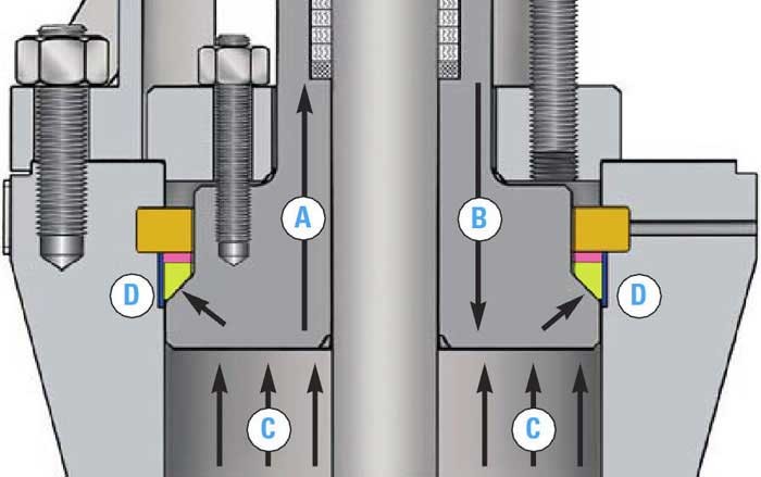
- A/B - Bonnet tendency to move up or down as pressure changes
- C - System pressure
- D - Sealing forces due to pressure
The sealing force increases with increasing internal pressure. The Bonnet assembly can be easily disassembled by dropping it into the body cavity and using a push pin to drive out the four-segmental thrust rings.
As boiler, HRSG, and pipe system pressure/temperature envelopes are pushed further by designers, pressure seal valves—which rely on comparatively straightforward design principles—have demonstrated their capacity to manage progressively more demanding fossil and combined-cycle steam isolation applications. Pressure seal valves are generally offered in size ranges of 2 to 24 inches and ASME B16.34 pressure classes of 600 to 2500; however, certain manufacturers can fulfill special application requirements that require larger diameters and higher ratings.
Pressure seal valves come in a variety of material qualities, including F316H forged and appropriate austenitic cast grades for temperatures above 500°C; A105 forged and Gr. WCB cast; alloy F22 forged and Gr. WC9 cast; F11 forged and Gr. WC6 cast; and austenitic stainless F316 forged and Gr. CF8M cast.
The origins of the pressure seal design concept date back to the mid-1900s, when valve manufacturers started developing alternatives to the conventional bolted-Bonnet method of sealing the body/Bonnet joint due to constantly rising pressures and temperatures (mainly in power applications). In addition to offering superior pressure boundary sealing integrity, numerous pressure seal valve designs were substantially lighter than their bolted Bonnet Valve equivalents. Let's compare the body-to-Bonnet sealing mechanism of pressure seals and bolted Bonnets in order to better understand the pressure seal design concept. The typical Bolted Bonnet valve is shown in Fig. 1. A gasket of the appropriate design or material is inserted between the flange faces to aid in sealing, and the body and bonnet flanges are fastened together with studs and nuts. To achieve the best sealing, studs, nuts, and bolts are tightened to specified torques according to a pattern specified by the manufacturer. On the other hand, the possibility of leakage through the body/Bonnet joint also rises with system pressure.
Let's now examine the pressure seal joint that is shown in Fig. 2. Take note of how the various body/Bonnet joint configurations differ. "Bonnet take-up bolts" are a common feature of pressure seal designs, which enable the bonnet to be pulled up and sealed against the pressure seal gasket. Consequently, a seal is formed between the gasket and the valve body's inner diameter (I.D.).
The thrust ring is segmented to maintain the load. The pressure seal design is so beautiful because it increases the load on the Bonnet and, by extension, the pressure seal gasket, as system pressure rises. As a result, in pressure seal valves, the possibility of leakage through the body/bonnet joint diminishes with increasing system pressure.
When it comes to main steam, feedwater, turbine bypass, and other power plant systems that need valves that can withstand the difficulties of high pressure and temperature applications, this design approach has clear advantages over bolted Bonnet Valves.
However, the same transient system pressure that helped in sealing also severely harmed the integrity of the pressure seal joint as operating pressures and temperatures rose over time and peaking plants were introduced. The gasket itself is one of the main parts that seals the pressure seal valve. Iron or soft steel were used to make pressure seal gaskets in the past. To take advantage of the softer plating material's ability to create a tighter seal, these gaskets were then silver-plated. The pressure used during the hydrotest of the valve resulted in a "set"—a deformation of the gasket profile—between the gasket and the bonnet. The Bonnet had the potential to move and break that "set" when subjected to system pressure increases or decreases because of the inherent elasticity of the pressure seal joint and take-up bolt. This could lead to body/Bonnet joint leakage.
The practice of "hot torquing" the Bonnet take-up bolts following system pressure and temperature equalization could effectively eliminate this issue, but it required maintenance staff from the owner/user to perform this action following plant startup. Failure to follow this procedure could result in leakage through the body/Bonnet joint, damaging the pressure seal gasket, the Bonnet, and/or the valve body's I.D. in addition to exacerbating issues and potentially impairing plant operations due to steam leakage. Consequently, the designers of Valve implemented multiple measures to tackle this issue.
In Figure 2, a combination of live-loaded Bonnet take-up bolts (which minimize the possibility of leakage by maintaining a constant load on the gasket) and a die-formed graphite pressure seal gasket in place of the iron/soft steel, silverplated one are shown. Pressure seal valves that were previously supplied with the conventional type gasket can now be equipped with the gasket design depicted in Figure 3. The introduction of graphite gaskets has strengthened the pressure seal valve's dependability and performance in the majority of applications, including daily start/stop operation cycles.
While many manufacturers still advise against "hot torquing," doing so significantly reduces the likelihood of leaks. Similar to many power plant valves, the seating surfaces of pressure seal valves experience relatively high seating loads. Tight machining tolerances on component parts, a way to supply the necessary torque to open or close in response to gears or other actuation, and the choice and use of suitable materials for seating surfaces are the three factors that maintain seat integrity.
Hardfacing alloys based on cobalt, nickel, and iron are used to provide the best possible wear resistance for the wedge/disc and seat ring seating surfaces. The CoCr-A (Stellite, for example) materials are the most widely utilized. A range of techniques, such as shielded metal arc, gas metal arc, gas tungsten arc, and plasma (transferred) arc, are used to apply these materials. While gate valves and check valves usually have hardfaced seat rings that are welded into the valve body, many pressure seal globe valves are designed with integral hardfaced seats.
Terminology valuation
If you've worked in the valve industry for any amount of time, you've undoubtedly noticed that the terminology and vernacular used by valve manufacturers are not very inventive. For instance, consider "bolted Bonnet Valves." To preserve the integrity of the system, the body is bolted to the Bonnet. In "pressure seal Valves," the sealing mechanism is aided by system pressure. For "stop/check Valves," the flow is mechanically stopped when the valve stem is closed; however, when the stem is open, the disc can move freely to check a reversal of flow. The same idea holds true for other design jargon as well as valve kinds and their constituent parts.
