For large differential pressure applications or in situations where thermal expansion could result in wedge-type sticking, parallel slide construction can be provided. Two replaceable spring-loaded discs, a completely guided disc holder, and retaining pins make up the parallel sliding gate assembly. Springs are installed between discs just to supply the initial sealing force; the sealing force is not maintained. Because the discs are interchangeable, there is no need to custom fit the seats to the discs, which streamlines in-line maintenance. Position sitting removes any binding and stress brought on by the stem's thermal expansion.
No more torque is required to produce a firm seal once the discs are in position. Reduce actuator size and cost by lowering seating torque. High cycle capability in extremely high differential pressure services is offered by hardfaced seating surfaces. The transverse differential pressure across the valve seat is decreased by using bypass valves. In addition to reducing the size of the operational equipment, it offers a practical way to warm pipe lines initially.
In addition to providing an outlet for the fluid displaced by the valve stem traveling to the shut position, equalizing mechanisms are utilized to release the fluid trapped between the seat forces.
The dual-parallel-disc construction is used by the parallel slide gate valve. To open or close the fluid stream, the driving mechanism pushes the gate vertically. The bore of the gate is the same as the inner diameter of the pipe. The stem and gate can be raised or lowered by turning the handwheel or turning on the actuator. Fluid flows (valve opens) when the gate bore lines up with the pipeline. The valve closes when the gate stops the flow passage (the bore retracts into the valve chamber).
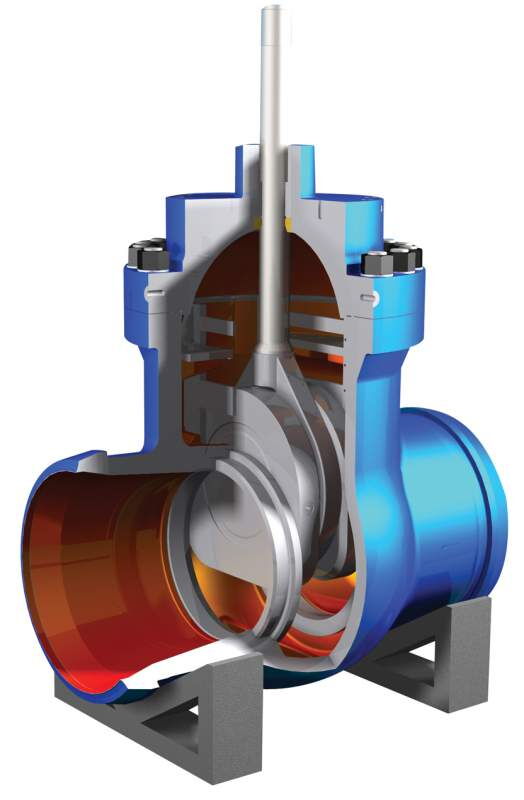
The body, which houses parallel gate discs, is made of carbon steel, stainless steel, etc. and is cast or forged. Sealing is improved by the dual-disc design. Flow is controlled by vertical disc movement.
Through threads, the alloy or stainless steel stem is attached to the gate. Bidirectional sealing is ensured by sealing components such as graphite rings, PTFE, or hardfaced alloy seats.
Actuators that offer manual, electric, or pneumatic operation adhere to API 6D specifications. There are options that won't explode.
includes pre-loading floating chairs for two-way sealing. Materials: PTFE and reinforced graphite.
Yoke Sleeve: Operating torque is decreased by aluminum bronze.
Seat Ring: welded for effortless upkeep.
Vented vs. Non-Vented Parallel Slide Gate Valves
The main distinctions are found in application, function, and structure. In lengthy pipelines, vented valves feature a hole for seat protection, pigging, and pressure release. Non-vented valves work well with sealed systems that don't require pigging.
• Vent Hole Design:
Vented: A hole in the lower disc of nominal size. When the hole is fully open, it aligns with the seat to relieve pressure and flow.
No hole: Non-Vented. When open, the seat groove is exposed to the media.
• Seal Protection:
Vented: The hole prolongs the life of chairs by shielding them from direct media erosion.
Non-Vented: Less reliable; seats may deteriorate when left open.
| Comparison Factor | Vented Parallel Slide Gate Valve | Non-Vented Parallel Slide Gate Valve |
|---|---|---|
| Typical Use | Oil/gas trunk lines, piggable pipelines | Power plant piping, pump inlets/outlets |
| Pigging Capability | Supports pigging operations | Cannot be pigged |
| Operating Effort | Low (pressure relief reduces cavity pressure) | Higher operating resistance |
• Pressure Relief: Prevents overpressure from medium expansion by expelling cavity pressure upstream.
• Flow Efficiency: Smooth flow path with minimal pressure decrease (perfect for natural gas and crude oil).
• Maintenance: By removing pipe deposits, pigging shortens downtime.
• Sealing Structure: Bidirectional sealing is made possible by O-ring seals and pre-loaded floating seats. Compared to normal valves, the operating torque is 50% lower.
• Structure of Packing: Packing that seals itself requires little modification. Reliable sealing and light operation. Zero leakage is ensured via auxiliary grease injection..
• Flow channel Design: A straight, full-bore flow channel reduces pressure loss. allows for pipeline pigging.
• Protection: A completely protected building that can function in any weather.
• A pressure relief device guards against internal harm from excessive pressure.
• Classification:
By Drive: Manual, Pneumatic, Electric.
By Function: Vented, Non-Vented, Oilfield, Pipeline, Gas.
→Oil and Gas: Primary valves for the transmission of natural gas and crude oil (up to 15.0MPa). utilized in storage and blowdown systems. conforms to API 6D.
→ Chemical Industry: Uses PTFE/graphite seals to control corrosive media (acids, slurries).
→ Power Industry: Controls the flow of steam and cooling water in hydro, nuclear, and thermal plants. maximizes the use of energy.
→ Municipal and environmental: regulates gas and wastewater in systems for treatment and discharge. used in the drainage and supply of water.
→ Other Industries: Sanitary fluid control (food), sterile media isolation (pharma), and high-purity metal transfer (metallurgy).
1.Low Flow Resistance: A short pipe section's resistance is determined by the straight full-bore design. high capacity for flow.
2.Excellent Sealing: Leak-tight closure is ensured by dual-sealing discs made of metal and soft seat composite. manages variations in temperature and pressure.
3. Simple Structure: Simple to manufacture and maintain. low cost of lifespan.
4. Wear Resistance: In abrasive media, hard-faced chairs prolong service life.
5. Broad Applicability: Fits a variety of media, including oil, gas, acids, and slurries, at temperatures ranging from -196°C cryogenic to +550°C steam.
6.Low Operating Torque: Manual operation that is effortless.
7.Bidirectional Sealing: Security against zero leaks.
1. Not for Throttling Flow: For ON/OFF service only. Seats degrade when partially opened.
2.Sensitivity to Poor Flow Control: Only about 50% of the open position has effective flow control.
3. Disc vibration is a possibility when closing against a flow with a high velocity or density.
1.Match the valve material to the media to ensure media compatibility.
• Acids/Alkalis → Stainless steel / PTFE-lined.
• Abrasive Slurries → Tungsten carbide-coated disc.
• Cryogenic Service → Verify material toughness at low temps.
2. Pressure & Temperature: Ensure valve rating covers operating conditions:
• Class 150: -29°C to 425°C
• Class 600: -196°C to 550°C
• Class 1500: -29°C to 650°C
3. Structure Type:
• Rising Stem: For frequent operation/pigging access.
• Non-Rising Stem: For infrequent operation/limited space.
4. Method of Actuation: Other factors to take into account include maintenance access, leakage class, CV (flow coefficient), and operating requirements.
• Manual: Small valves or backup.
• Electric/Pneumatic: Large valves (DN300+).
• Explosive Areas → Pneumatic/Hydraulic or explosion-proof electric.
• Manual valves: Add gearbox for high torque.
